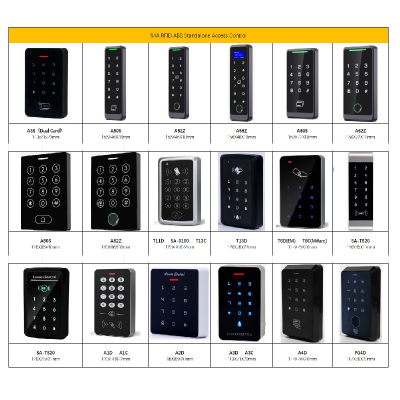
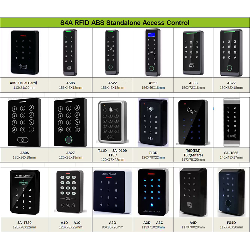
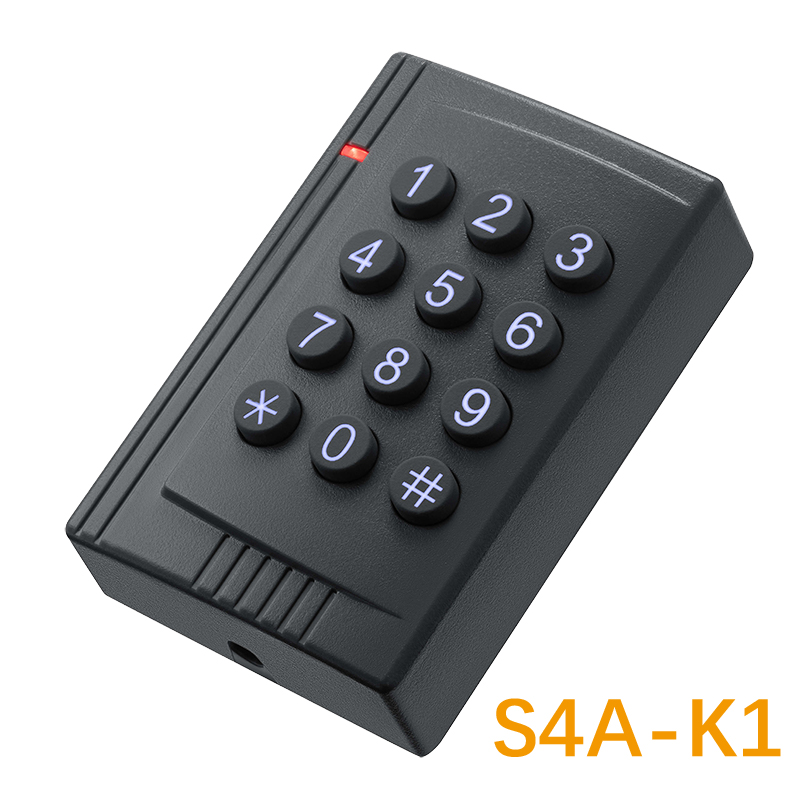
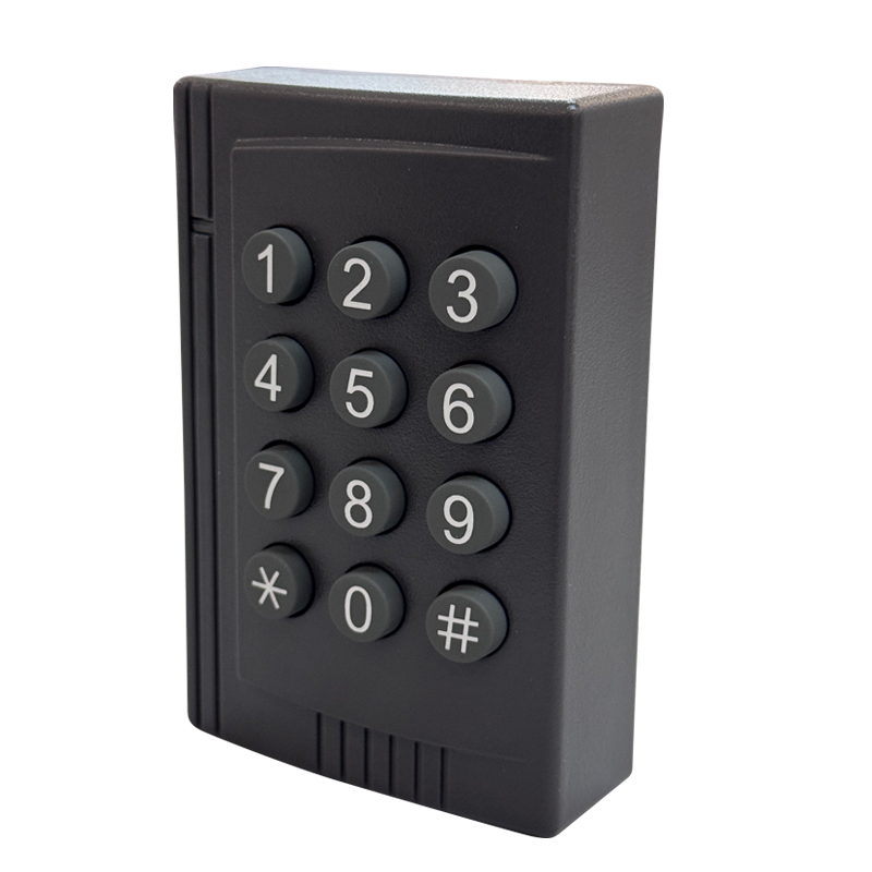
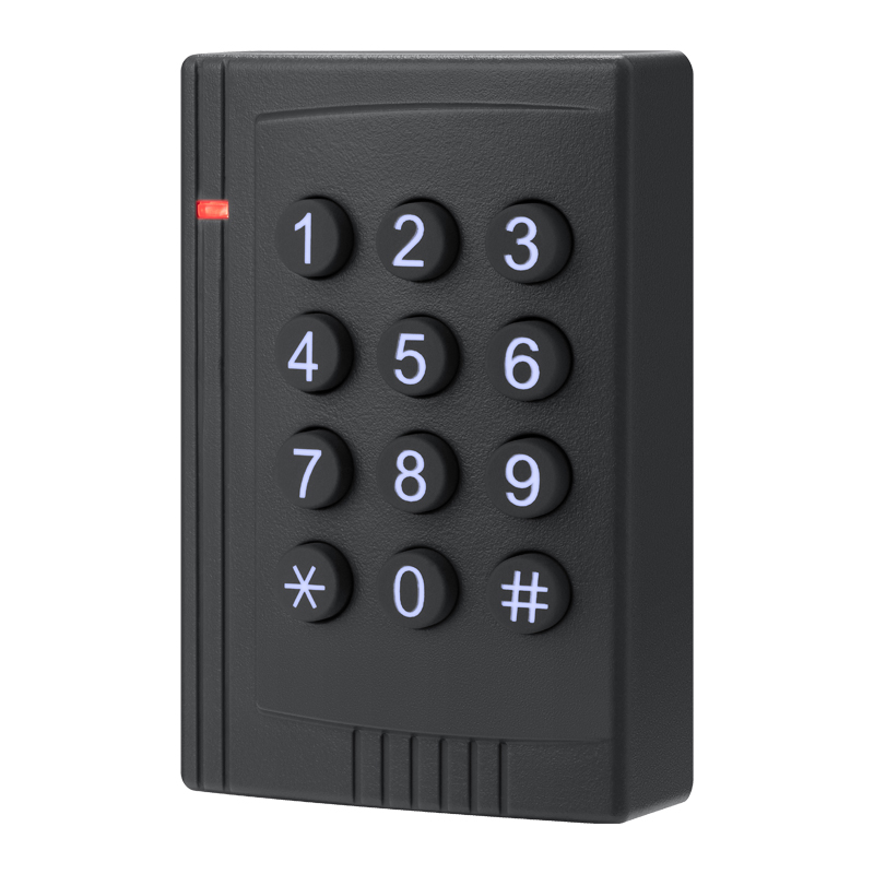
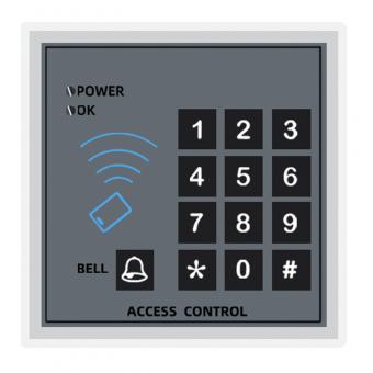
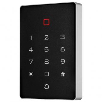
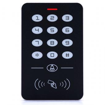
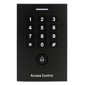
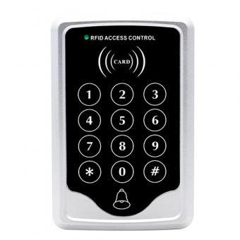
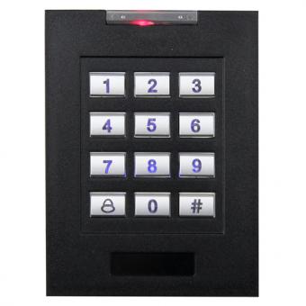
Access Control Keypads (Stand Alone)
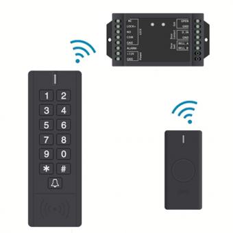
Wiring a standalone access controller involves connecting power, the keypad or reader, the lock, and optional accessories (e.g., door sensors, exit buttons). The exact steps depend on the controller model and manufacturer, but here's a general guide with key considerations and diagrams to simplify the process:
Tools and Materials are Needed:
-
Wire stripper/crimper
-
Multimeter (for testing connections)
-
Low-voltage wires (18–22 AWG, stranded copper for flexibility)
-
Screw terminals, crimp connectors, or wire nuts
-
Conduit or cable clips (for wire protection)
-
Power supply (if not battery-powered)
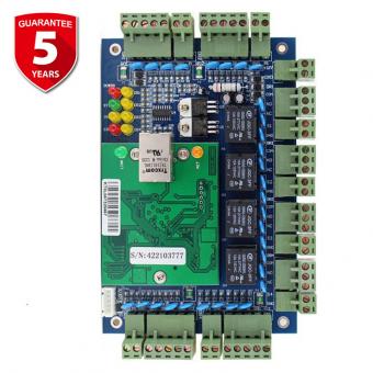
Step 1: Understand the Controller's Wiring Diagram
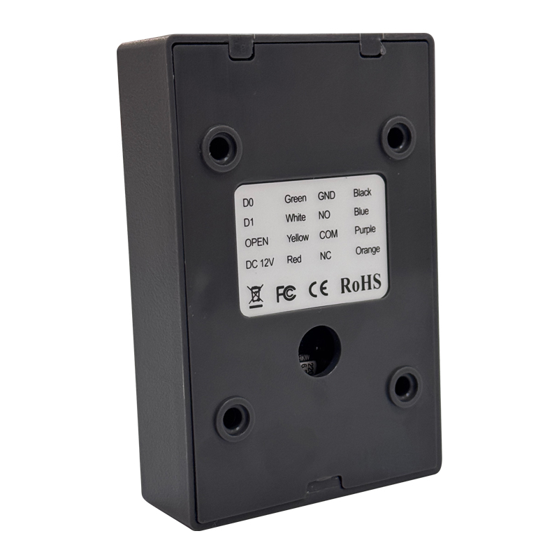
Most standalone controllers have labeled terminals for key components. Always refer to the manufacturer's manual for exact terminal labels and voltage requirements. A typical layout includes:
-
Power Input: +12V DC, GND (ground)
-
Keypad/Reader: DATA, COM (common), or specific pins (e.g., D0, D1 forwiegand readers)
-
Lock Output: LOCK+, LOCK- (for magnetic locks) or NC/NO (normally closed/normally open for electric strikes)
-
Accessories: DOOR (door sensor), REX (request-to-exit button), ALARM (alarm output)
Example Terminal Layout:
| Terminal Label | Function |
| +12V | Power input (positive) |
| GND | Power input (negative/ground) |
| DATA | Data signal from keypad/reader |
| COM | Common ground for keypad/reader |
| LOCK+ | Positive connection to lock |
| LOCK- | Negative connection to lock |
| DOOR | Connects to door sensor (normally closed) |
| REX | Connects to exit button (momentary switch) |
Step 2: Wire the Power Supply
A. Battery-Powered Controllers
-
No permanent wiring needed for power. Insert batteries (e.g., 4x AA) into the controller's battery compartment.
-
Optional wired backup: If the controller supports it, connect a 12V DC power supply to the +12V and GND terminals using 18–22 AWG wires. Ensure correct polarity (red wire to +12V, black to GND).
B. Hardwired Power Supply
-
Connect the power supply's output to the controllers' +12V and GND terminals.
-
Use a regulated power supply (e.g., 12V DC, 1A) and ensure the total current draw of the controller, keypad, and lock does not exceed the supply's capacity.
-
For long runs, use thicker wire (18 AWG) to minimize voltage drop.
Step 3: Connect the Keypad or Reader
A. Wiegand Keypad/Reader (Common for Standalone Systems)
-
Wiegand protocol uses two data wires (DATA0, DATA1) and a common (COM).
-
Connect the keypads DATA0 to the controllers DATA terminal (or D0), DATA1 to D1 (if labeled), and COM to the controllers COM terminal.
-
Use shielded twisted-pair wire to reduce interference, especially for runs over 20 ft (6 m).
B. Simple Keypad (Direct Connection)
-
Some standalone controllers have dedicated terminals for keypad rows and columns (e.g., R1–R4, C1–C3). Follow the manual to map keypad buttons to these terminals.
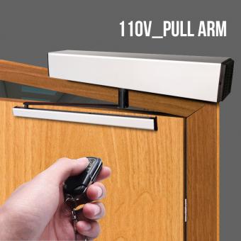
Step 4: Wire the Lock
A. Magnetic Lock (Fail-Secure)
-
Magnetic locks require a continuous power supply to stay locked (fail-secure: locks when power is on, unlocks when power is off).
-
Connect the locks positive (+) wire to the controllers LOCK+ terminal and negative (-) to LOCK-.
-
Ensure the controllers' lock output voltage matches the locks requirements (e.g., 12V DC, 24V DC).
B. Electric Strike (Fail-Safe or Fail-Secure)
-
Fail-safe strike: Unlocked when power is on (common for emergency egress).
-
Fail-secure strike: Locked when power is on (standard for security).
-
Connect the strike to the controllers NC (normally closed) or NO (normally open) terminals based on the fail-safe/fail-secure mode:
-
Fail-safe: Use NO terminals (strike unlocks when power is applied).
-
Fail-secure: Use NC terminals (strike locks when power is applied).
Step 5: Add Optional Accessories
A. Door Sensor (Contact Switch)
-
Install a normally closed (NC) door sensor to monitor door status (open/closed).
-
Connect one sensor wire to the controller's DOOR terminal and the other to GND (or COM, per manual).
-
The controller will trigger an alarm if the door is forced open (sensor opens).
B. Request-to-Exit (REX) Button
-
A momentary push button allows users to exit without a code.
-
Connect the REX buttons' two wires to the controller's REX and GND terminals. Pressing the button sends a signal to unlock the door.
C. Alarm Output
-
If the controller has an ALARM terminal, connect it to a siren or buzzer using 22 AWG wires. The alarm triggers on unauthorized access or forced entry.
Step 6: Ground the System (Optional but Recommended)
-
For outdoor or high-interference environments, ground the controller's metal enclosure to a building ground using a 14–16 AWG green wire.
-
Connect one end to the controller's GND terminal and the other to a grounding rod or the electrical panel's ground bus.
Step 7: Route and Protect Wires
-
Indoor wiring: Use cable clips to secure wires along walls or baseboards. Avoid exposing wires to foot traffic or physical damage.
-
Outdoor wiring: Run wires through PVC conduit to protect against moisture, UV rays, and pests. Seal conduit ends with weatherproof glands.
-
Separate power and data wires: Keep power cables at least 6 inches (15 cm) away from data cables to prevent interference.
Step 8: Test the System
-
1. Power on the controller: Check for error lights (e.g., red LED for low voltage).
-
2. Test the keypad: Enter a user code to ensure the controller beeps and the lock activates.
-
3. Lock/unlock function: Verify the lock engages and releases when a valid code is entered.
-
4. Door sensor: Open/close the door to check if the controller detects the status (e.g., green LED for “door closed”).
-
5. REX button: Press the exit button to confirm the lock release.
-
6. Troubleshoot: If issues arise, use a multimeter to check voltage at the lock and controller terminals, and reverify wire connections.
Key Tips
-
Label wires: Use a label maker to mark wires (e.g., “LOCK+,” “REX”) for easy future maintenance.
-
Follow polarity: Reverse power connections can damage the controller or lock.
-
Check voltage drop: For long wire runs, measure voltage at the lock to ensure it's within 10% of the rated voltage (e.g., 12V DC ±1.2V).
-
Refer to the manual: Each controller has unique features (e.g., time zones, anti-passback). The manual will detail specific wiring for advanced functions.
By following these steps and prioritizing safety and clarity, you can successfully wire a standalone access control system. Always power off the system before making connections, and consult a professional if unsure about electrical work. There is a professional team in S4A that can solve your problems with wiring and hardware.


 English
 français
 Deutsch
 русский
 italiano
 español
 português
 العربية
 Türkçe
 Tiếng Việt
 Indonesia


")
")

 IPv6 network supported